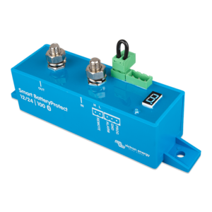
Victron Energy Smart BMS 12/200
Algne hind oli: 300.00 €.260.00 €Current price is: 260.00 €.
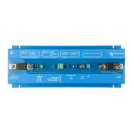
The Smart BMS 12/200 is an all-in-one Battery Management system for Victron Lithium-Iron-Phosphate (LiFePO4) Smart Batteries. It has been specifically designed for 12V systems with a 12V alternator such as in vehicles and boats.
It combines a Current Limiter, Battery Combiner and Battery Protector in a robust and compact solution and lets you safely connect any size 12V alternator (and starter battery), loads and chargers to Smart Lithium batteries.
- Kirjeldus
- Kirjeldus
Kirjeldus
The Smart BMS 12/200 monitors and protects each individual battery cell within the battery (or battery bank) and will disconnect the alternator, charge sources or DC loads in case of low battery cell voltage, high battery cell voltage or over temperature.
The dedicated alternator connection provides current limiting and one-way traffic from the alternator into the battery, this so any size alternator (and starter battery) can be safely connected to the Smart Lithium battery (or battery bank) and the starter battery is protected from excessive discharge.
The BMS is equipped with Bluetooth for monitoring and configuration, a remote on/off connector, to turn the BMS (and the system) off via a remote switch and a pre-alarm contact, to give a warning signal before the BMS will disconnect the batteries from the system.